Driven by the "dual carbon" goals and the global energy transition, microgrid systems are evolving from concept to reality, becoming stabilizers and optimizers of power supply in industrial, commercial, and residential scenarios. However, power supply requirements vary significantly across different scenarios: factories must cope with peak and off-peak price fluctuations, high-end villas strive for quiet and aesthetically pleasing design, and data centers require millisecond-level power continuity. As a professional battery energy storage solutions provider, GreenMore, leveraging over a decade of experience in power conversion technology, has launched customized microgrid systems covering light, medium, and high-load scenarios. With a core focus on scenario adaptation, GreenMore offers global customers precise, flexible, and intelligent power solutions.
1. Small microgrid system
Applicable scenarios: factory office areas, hotels, high-end villas, scenic area facilities and other low-power electricity consumption scenarios.
Core advantages:
1)Three-phase 100% unbalanced load, stable supply in fluctuating scenarios
Traditional microgrids are prone to power outage risks when a single-phase load is too heavy. However, the GreenMore small system uses dynamic power distribution technology to support completely unbalanced operation of three-phase loads. Even if the load on one phase suddenly increases by 50%, the system can still maintain stable output, avoiding global power outages caused by local power fluctuations.
2)Intelligent environmental adaptation, no fear of harsh working conditions
For humid and dusty environments, the system features a built-in intelligent temperature control and condensation removal module and multi-layer filter protection, ensuring stable operation in temperatures ranging from -20°C to 55°C and at 95% humidity. For example, after adopting this system at a high-end villa project in Bali, the annual equipment failure rate due to salt spray corrosion decreased by 90%.
3)Modular design, expansion is like building blocks
By adopting a modular architecture with multiple units connected in parallel, users can flexibly add battery cabinets or inverters based on their needs. When a scenic spot added new charging stations during peak season, they simply connected three 10KWh energy storage units in parallel, doubling their power capacity and reducing costs by 65% compared to building a new substation.
2. Medium-sized microgrid system
Applicable scenarios: medium-scale power consumption scenarios such as temporary power supply at construction sites, mining, shopping malls, and remote overseas projects.
Core advantages:
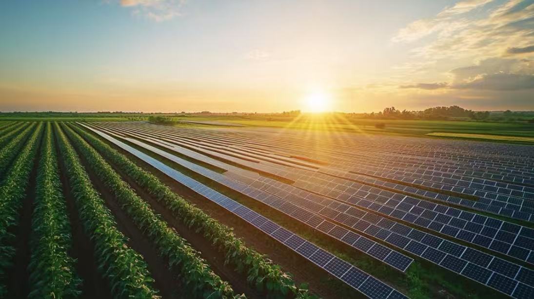
1)Maximum access to 720kW photovoltaic power, achieving “zero waste” in new energy consumption
Medium-sized microgrid systems support the complementary use of photovoltaic power, diesel generators, and utility power, making them particularly suitable for areas with abundant sunlight but limited grid coverage. In a mining project in Africa, the system prioritized photovoltaic power, reducing diesel generator operating time by eight hours per day and saving over $150,000 in annual fuel costs.
2)Intelligent protection design to deal with temporary power outage risks
Over 10 built-in safety mechanisms, including overload, short-circuit, and islanding protection, automatically isolate faulty modules to ensure continuous power to the remaining systems. When a lightning strike caused a mains power outage at a construction site, the system switched to backup power within 0.02 seconds, preventing a potential safety incident caused by a tower crane outage.
3)Standard container deployment shortens overseas project cycles
Designed using a 40-foot standard container, the system supports full container load (FCL) delivery by sea. Overseas projects can achieve a mere 30 days from shipment to grid connection, a 50% improvement compared to traditional construction methods. In a Southeast Asian shopping mall renovation project, the system was quickly installed via container hoisting, achieving a zero-construction power upgrade.
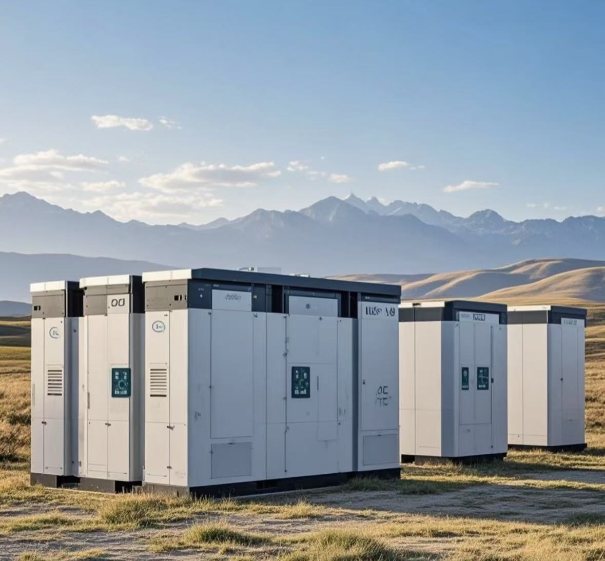
3. Large-scale microgrid systems
Applicable scenarios: Industrial parks, data centers, hospitals, and other scenarios with extremely high requirements for power supply continuity.
Core advantages:
1)Multi-layer fire protection + real-time health detection, zero compromise on safety
Equipped with a gas fire extinguisher, temperature sensors, and an AI-powered fault prediction algorithm, the system provides 72 hours of advance warning of battery thermal runaway risks. After implementing this system, one data center achieved zero power outages for three consecutive years and received Uptime Tier IV certification.
2)Network-based PCS + grid support to enhance grid resilience
By simulating the characteristics of synchronous generators, the system can proactively adjust voltage and frequency when multiple businesses are connected in parallel or using electricity in a centralized manner, mitigating grid fluctuations caused by the integration of renewable energy sources. In an industrial park in Jiangsu, the system successfully supported the simultaneous startup of high-power equipment at 20 businesses, keeping voltage fluctuations within ±1%.
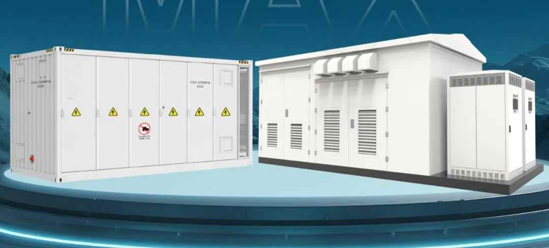
3)Highly integrated design, saving land and costs
Using liquid cooling technology and 3D wiring, the system's power density is increased by 40%. A 10MWh energy storage system requires only 200 square meters of space, saving 30% in land costs compared to traditional solutions. In a chemical park in Guangdong, the integrated design reduced cable laying by 60%, shortening the installation cycle to 15 days.
4. GreenMore: Redefining the value of microgrids with customized capabilities
After more than a decade of development, GreenMore's microgrid systems have been deployed in over 20 countries worldwide, with over 500 projects delivered. We understand that there is no "one-size-fits-all" microgrid, only "precisely adaptable" solutions.
- Technology customization: supports on-demand adjustment of parameters such as capacity, power, and communication protocols;
- Service customization: providing full life cycle services from solution design, installation and commissioning to operation and maintenance training;
- Eco-customization: Cooperate with more than 100 solar dealers and system integrators around the world to ensure rapid local response.
In the second half of the energy revolution, GreenMore will continue to use scenarios as anchors and technology as sails to help global customers build a safe, efficient and sustainable power future!
Visit our website www.gmsolarkit.com to get your exclusive microgrid solution!