From Concentration to Resource Recovery The Core Role of Electrodialysis in Industrial Wastewater Zero Liquid Discharge (ZLD)

Driven by the dual-carbon targets and national wastewater resource recovery strategy, industries are heavily investing in green transitions. Alongside zero liquid discharge (ZLD) for wastewater, adopting hydrogen fuel cell systems for clean energy has become another inevitable technical route for water-intensive and heavily polluting industries. The core principle of ZLD is straightforward: fully separate clean water from pollutants in wastewater to realize water reuse, while pollutants are treated as solid residues for disposal or resource recovery. Nevertheless, implementing ZLD faces prominent technical bottlenecks, especially for high-salinity wastewater which constitutes the bulk of industrial effluents. Maximizing brine concentration at minimal energy cost is the decisive factor governing the economic viability of the entire ZLD system.


Against this backdrop, electrodialysis (ED) technology stands out thanks to its unique technical merits and is gaining an increasingly central position in full-scale ZLD processes.


1. Necessity of Electrodialysis for ZLD Systems

Conventional ZLD processes mainly adopt the combined process of reverse osmosis (RO) + evaporative crystallization. RO delivers preliminary desalination and concentration, yet its concentration ratio is constrained by osmotic pressure. Once the total dissolved solids (TDS) of wastewater rise to a threshold, further boosting operating pressure triggers skyrocketing power consumption and raises risks of irreversible mechanical damage to RO membranes. Consequently, large volumes of under-concentrated brine are fed into evaporators. Evaporation is universally recognized as the most energy-intensive and costly unit operation across the whole ZLD workflow.

Electrodialysis precisely fills the concentration gap between RO and thermal evaporation. Unlike pressure-driven RO, ED relies on an applied electric field to drive directional ion migration, enabling high-fold concentration under ambient temperature and atmospheric pressure with far higher tolerance to influent salinity. Installing ED as an intermediate stage after RO and ahead of evaporative crystallization drastically cuts down the brine volume sent to evaporators without excessive incremental energy input.


2. Core Functions of Electrodialysis in ZLD Projects

(1) Deep Brine Concentration

Deep concentration represents ED’s primary function in ZLD facilities. Brine concentrated via pre-treatment processes such as RO flows into ED stacks for secondary or even tertiary concentration, pushing salinity close to saturation before thermal crystallization. This tiered "membrane concentration + thermal concentration" design minimizes the feed volume of high-energy evaporation units, which has become the mainstream engineering paradigm for modern ZLD projects.

(2) Selective Salt Separation and Resource Valorization

Many industrial wastewaters contain mixed dissolved salts. Direct crystallization of mixed salts yields low-value mixed solid waste that must be handled as hazardous waste with substantial disposal costs. Selective electrodialysis separates ions of different valence states under electric potential. For instance, selective ED effectively segregates corrosive chloride ions (Cl⁻) and sulfate ions (SO₄²⁻) in steel mill wastewater. The separated high-purity saline streams can be further refined and recycled as industrial raw materials.

Furthermore, bipolar membrane electrodialysis (BPED) directly converts waste brine into corresponding acids and alkalis. These regenerated chemicals can be recycled on-site for pH adjustment, ion exchange resin regeneration and other production procedures, achieving genuine resource recovery from saline wastewater.


3. Technical Limitations & Practical Engineering Considerations

Electrodialysis is not a universal all-in-one solution. Stable and efficient ED operation requires strict pre-treatment of influent: suspended solids, scale-forming hardness ions and organic contaminants must be removed to meet influent standards; otherwise, severe membrane fouling and scaling will occur and degrade stack performance. Although ED accommodates higher influent TDS compared with RO, excessively high initial salinity reduces current efficiency and weakens concentration performance. Accordingly, process parameters must be customized based on site-specific water quality data. In real-world engineering applications, ED is integrated with chemical softening, nanofiltration (NF), RO, evaporative crystallization and other treatment units into a complete integrated ZLD system, where each unit undertakes dedicated functions and operates synergistically.


4. Conclusion

The core objective of industrial wastewater ZLD is to strike a balanced trade-off between environmental compliance and economic sustainability. The core advantage of electrodialysis lies in substituting a portion of high-cost thermal energy consumption with relatively low-cost electrical energy, enabling cascaded energy utilization throughout the whole ZLD system. With continuous advancement in ion exchange membrane materials and accumulation of field engineering experience, ED has evolved from an optional auxiliary module to an indispensable core unit within ZLD workflows. It cannot eliminate all wastewater treatment challenges, but it perfectly addresses the critical bottleneck of volume reduction for high-salinity brine. For enterprises planning or constructing ZLD facilities, mastering and properly deploying electrodialysis technology is a pivotal step to turn the conceptual goal of zero liquid discharge into feasible industrial practice.

Continue
How a Membrane Separates Chlorine and Alkali — Working Principle of Ion-Exchange Membrane Electrolysis Cells

Salt (NaCl) is dissolved in water, and direct current is applied. At the anode, yellow-green chlorine gas is released; at the cathode, hydrogen gas is produced, and sodium hydroxide (NaOH) forms in the solution. Overall reaction: 2NaCl + 2H₂O ⟶ 2NaOH + Cl₂↑ + H₂↑


This reaction does not occur spontaneously — it requires at least 2.19 volts to drive it. The higher the temperature, the lower this minimum voltage, so the electrolysis cell operates at 85–90°C. But the temperature cannot be raised indefinitely, because the membrane that plays the critical role cannot withstand it.


The real challenge of electrolysis is not applying current, but separating the products the moment they are born. If chlorine gas and caustic soda meet, they immediately react back into bleach; if chlorine gas and hydrogen gas mix, they may explode. Major accidents in the chlor-alkali industry almost always trace back to this root cause.


Over the past century, three separation approaches have been developed. The earliest, the mercury process, used flowing liquid mercury as the cathode — sodium dissolved into the mercury to form a liquid alloy, which was pumped to an adjacent room to react with water and produce caustic soda; chlorine and alkali never shared the same chamber, at the cost of mercury's toxicity. The diaphragm process sandwiched a porous asbestos pad between the two electrodes, with brine flowing from anode to cathode, using the flow to prevent caustic soda from flowing back — simple and cheap, but the caustic soda was heavily contaminated with salt, requiring subsequent evaporation and purification. The membrane process is fundamentally different: it uses a dense polymer membrane filled with negative charges that naturally repels negatively charged OH⁻ and Cl⁻, allowing only Na⁺ to pass through.


The structure of a membrane electrolysis cell is a sandwich: titanium mesh anode (coated with ruthenium-iridium oxide) → membrane → nickel mesh cathode. Modern “zero-gap” designs press the electrodes elastically against the membrane, leaving no gap — the gas bubbles generated during electrolysis would cover the electrodes and increase resistance; the zero-gap design allows bubbles to escape through grooves on the back of the electrodes, saving considerable electrical power.


Within the multilayer structure of this membrane, the most critical component is the carboxylic acid layer facing the cathode, which is extremely thin. The carboxylic acid groups (–COOH) are weak acids with a pKa of approximately 2–3. On the acidic anode side (pH 2–4), a large proportion of –COOH groups remain as neutral molecules, with ion channels half-open; on the alkaline cathode side (pH > 14), all –COOH groups dissociate into –COO⁻, forming a dense wall of negative charges that blocks OH⁻ firmly. The membrane exploits the natural pH gradient on both sides — “opening the door” for conduction on the anode side and “closing the door” for blocking on the cathode side. A single-layer sulfonic acid membrane achieves only about 80% current efficiency; with the addition of this carboxylic acid layer, the efficiency jumps to 96–97%.


Driven by the electric field, Na⁺ migrates from concentrated brine through the membrane into concentrated caustic soda. Ideally, for every electron that flows, one Na⁺ crosses the membrane — this ratio equals the current efficiency. However, about 3–4% of the current is still carried by “escaping” OH⁻ — the OH⁻ concentration in the catholyte is a trillion times that in the anolyte, and the concentration-gradient-driven diffusion force is extremely strong. As Na⁺ crosses the membrane, it also drags 3–5 water molecules: the catholyte is thereby diluted and needs water replenishment, while the anolyte loses water and the NaCl becomes more concentrated — at the extreme, salt crystals precipitate and scratch the membrane.


The theoretical voltage is 2.2V, while actual operation is approximately 3.0V. The extra 0.8V breaks down into: anode overpotential, cathode overpotential, electrolyte resistance, membrane resistance (the largest source of loss), electrode and contact resistance, and bubble effects. As the membrane is made thinner, the cell voltage also decreases accordingly.


The membrane's requirements for brine purity are nearly stringent: the total calcium and magnesium entering the cell must not exceed 20 ppb. This is equivalent to dissolving no more than 50 grams of calcium chloride in a standard swimming pool of water — exceeding this amount will poison the membrane. The calcium and magnesium content of ordinary seawater is 200,000 times this value. Therefore, the brine requires two-stage purification: chemical precipitation (the order of reagent addition must never be reversed) reduces calcium and magnesium from several hundred ppm down to 5 ppm; chelating resin towers then capture the remaining ions, bringing the total below 20 ppb. Particular vigilance is needed for iodine — trace amounts of iodine in sea salt, after oxidation at the anode, form permanent precipitates within the membrane, which can cause up to 5% loss in current efficiency.

Operating an electrolysis cell is like turning five interlinked knobs simultaneously. Temperature 85–90°C: higher saves electricity but the membrane cannot tolerate it. Current density 3–6 kA/m²: higher means greater capacity but increased resistive losses. More concentrated brine means higher current efficiency but risks crystallization that scratches the membrane. Caustic soda concentration is approximately 32–35%. The hydrogen-side pressure must always be higher than the chlorine-side pressure, ensuring that if the membrane is breached, only hydrogen leaks into the chlorine side — never giving chlorine the opportunity to enter the hydrogen side and form an explosive mixture. If the chlorine-side pressure exceeds the hydrogen-side pressure: chlorine gas will penetrate the ion-exchange membrane or seals and leak into the hydrogen side. Chlorine mixing into hydrogen not only forms an explosive gas mixture but also causes severe corrosion to hydrogen pipelines and compressors. If the hydrogen-side pressure is higher than the chlorine-side pressure, even in the event of a minor leak, hydrogen will permeate toward the chlorine side. Although hydrogen mixing into chlorine also poses an explosion risk, chlorine systems are typically equipped with more comprehensive dehydrogenation and monitoring facilities. More importantly, under the industrial design principle of “Fail-Safe,” maintaining slight positive pressure on the hydrogen side is the last line of physical defense against the most dangerous scenario of “chlorine intruding into the hydrogen system.”


       From salt to chlorine gas, caustic soda, and hydrogen — the ion-exchange membrane, using a polymer membrane thinner than cling film, achieves unhindered passage for cations and impenetrable barriers for anions under the exquisite regulation of a pH gradient. Lowest energy consumption, purest products, and most environmentally friendly — these threefold advantages have made the membrane process the absolute mainstream of the modern chlor-alkali industry.

Continue
How Can Safety Design and On-Site Troubleshooting Be Achieved for Stationary Water-Cooled PEM Hydrogen-Fueled Power Generation Systems?

1. Overall System Configuration

The water-cooled PEM fuel cell power generation system consists of five independent modules: the fuel cell stack, the hydrogen supply module, the air supply module, the thermal management module, and the electronic control module. Each module is isolated from the others to prevent cross-interference between gas, water, and electricity, thereby mitigating safety risks at the system architecture level.

water-cooled PEM fuel cell power generation system

 Core Components

 Composition and Functions

PEMFC (Proton Exchange Membrane) Hydrogen Fuel Cell Stack

The core component of the system, this proton exchange membrane fuel cell stack converts the chemical energy of hydrogen and oxygen into electrical energy and serves as the core unit for power generation.

Hydrogen Supply Module

Hydrogen leak detector, vapor-liquid separator, hydrogen recirculation pump (for configurations of 10 kW and above), exhaust treatment device, etc., ensure that hydrogen enters the stack stably and safely, while exhaust gas is discharged from the system through the hydrogen exhaust port.

Air Supply Module

Comprising an air filter, intercooler, humidifier, air compressor, throttle valve, and various air ducts, this module supplies clean, dry air with a stable flow rate (the source of oxygen) to the stack, meeting the stack’s operational requirements.

Thermal Management Module

This module includes a water pump, radiator, temperature sensors, expansion tank, cooling fan, conductivity monitor, and deionizer. It controls the temperature of the fuel cell and all system components. Through forced-circulation water cooling, it promptly dissipates heat generated by the fuel cell, ensuring the system operates within the optimal temperature range and preventing damage caused by overheating.

Electrical Control Module

Utilizes a PLC controller equipped with a monitoring touchscreen to enable overall system control, parameter monitoring, fault diagnosis, and other functions.


 2. Structural Design

 In addition to the inherent safety design of the system modules, the stationary fuel cell power generation equipment features a meticulously designed structural layout that ensures operational safety and safe gas emissions, achieving separation between personnel and equipment and enabling manual intervention.


  stationary fuel cell power generation equipment


① Emergency Stop Button

        ② Inverter Control Panel

        ③ System Master Control Panel

        ④ Start Button (remains lit during normal operation)

        ⑤ Stop button (remains lit during a fault)

        ⑥ Early Warning Indicator (remains lit during warnings)


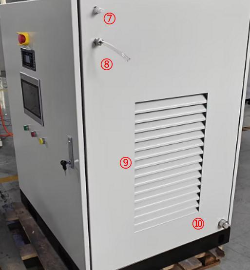
  stationary fuel cell power generation equipment


⑦ Hydrogen vent

        ⑧ Hydrogen Inlet

        ⑨ Heat dissipation vent

 ⑩ Exhaust and wastewater outlet


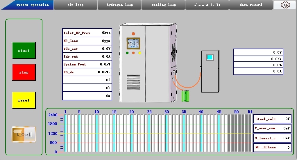
 3. Touchscreen Visual Monitoring

 The unit is equipped with an industrial-grade touchscreen display, eliminating the need for an external host computer. Six major functions—including equipment monitoring, parameter settings, manual debugging, and fault tracing—can be performed locally:

 Main Interface: Displays the equipment’s operating status (Running/Stopped/Fault Reset) and core parameters such as output power, voltage, current, hydrogen pressure, and cooling temperature.

 Air Circuit Page: Displays the operating status of the air compressor, fuel cell stack, DC-DC converter, and air control valve, including key parameters such as speed, power, and temperature.

 Hydrogen Circuit Page: Provides information on the status of the hydrogen inlet valve, proportional valve, purge valve (open/closed), and circulation pump.

 Cooling Circuit Page: Monitors the operating status of the cooling water pump (speed, pressure, and flow rate) as well as the radiator.

 Warnings and Faults Page: Displays the equipment’s historical fault records (fault codes, fault descriptions, and occurrence times) to facilitate troubleshooting and maintenance.

 Data Logging Page: Records various operational statuses of the system.

stationary fuel cell power generation equipment

The equipment supports manual control of operations such as startup, shutdown, purging, and hydrogen supply, making it suitable for use during commissioning and maintenance.


 4. On-Site Troubleshooting

 When a fault occurs during operation, the touchscreen interface automatically displays the fault code and description, enabling rapid troubleshooting and resolution; the equipment is equipped with a communication interface, and operational data can also be retrieved via this communication channel.

Fault Description

Possible Causes

Quick Fix

 High Anode Pressure Fault

 1. Malfunction of the external hydrogen pressure-reducing valve or failure of pressure stabilization;

 2. The hydrogen inlet solenoid valve does not close properly;
 3. Abnormal backpressure valve adjustment causing pressure buildup upstream;

 4. Hydrogen supply failed to adjust promptly due to sudden changes in load

 1. If the external hydrogen source is equipped with a pressure-regulating valve or pressure-reducing valve, re-calibrate or replace the hydrogen pressure-regulating valve or pressure-reducing valve;

 2. Check the sealing performance of the hydrogen solenoid valve; replace if defective;

 3. Fine-tune the backpressure valve opening to stabilize the pipeline pressure;

 4. Increase or decrease the load smoothly to match the hydrogen supply response

 Low Hydrogen Source Pressure Fault

 1. Insufficient pressure from the upstream hydrogen source;

 2. Leaks in the hydrogen piping or loose fittings;

 3. The pressure-reducing valve is stuck in the open position, causing restricted gas flow;

 4. Abnormal backpressure valve adjustment preventing hydrogen from flowing smoothly into the stack.

 1. Check the output pressure of the hydrogen cylinder or hydrogen supply equipment;

 2. Check for leaks and tighten pipe connections;

 3. Disassemble and clean the pressure-reducing valve spool, or replace the valve body;

 4. Check whether the backpressure valve is functioning properly.

High Hydrogen Concentration Malfunction

 1. Incomplete hydrogen purge and venting;

 2. The hydrogen concentration sensor has drifted and has not been calibrated;

 3. Gas leakage within the fuel cell or seal failure;

 4. Exhaust line blockage causing exhaust gas backflow

 1. Increase the purge frequency and duration;

 2. Recalibrate the hydrogen concentration sensor;

 3. Shut down the system to inspect the stack gaskets and end plate seals;

 4. Clear the hydrogen exhaust line to ensure unobstructed exhaust flow

 Air Compressor Malfunction

 1. Abnormal power supply to the air compressor, communication failure, or protection trip

 2. Air compressor overheating, insufficient coolant, water pump malfunction, or poor heat dissipation.

 3. Insufficient air flow due to a clogged air filter, air leaks in the piping, or abnormal rotational speed.

 1. Check whether the air compressor’s power supply is normal and verify that CAN communication is functioning properly.

 2. Check the operating status of the cooling system and radiator.

 3. Clean the filter element and check the air lines and speed feedback.

 Water pump flow rate is too low

 1. Water-cooling circulation pump failure or insufficient speed;

 2. Coolant lines are clogged or kinked, causing flow restriction;

 3. Significant air bubbles or air locks in the water circuit;

 4. Flow sensor is damaged / the throttle valve in the piping is partially closed

 1. Check the water pump’s power supply and drive; replace the water pump if necessary;

 2. Inspect the piping, clear blockages, and restore the pipe’s full cross-sectional area;

3. Open the bleed valve to force air out, then top off the coolant;

 4. Open the water circuit control valve and calibrate or replace the flow sensor

 Low Total Voltage Fault

 1. Insufficient hydrogen supply or low pressure

 2. Voltage drop due to excessive battery load

 3. Abnormal cell consistency or aging.

 4. High-power startup of the entire unit causes the bus voltage to drop

 1. Check whether the hydrogen supply pressure, pressure-reducing valve, and hydrogen piping are functioning normally and installed correctly.

 2. Reduce the system load and resume operation once the voltage has recovered.

 3. Inspect the battery and check for any abnormalities in its status.

 Low Voltage in Lowest Channel

 1. Insufficient system hydrogen supply

 2. Insufficient air supply

 3. Loose or faulty CVM sampling line

 4. CVM module communication or sampling failure

 5. CVM CAN bus communication line disconnection or abnormal terminating resistor;

 6. Damaged membrane electrode

 1. Check whether the pressure in the hydrogen and air lines is normal.

 2. Troubleshoot the CVM detection circuit.

 3. Check whether the CVM module is receiving power normally.

 4. Power off and restart the CVM module; if the issue persists, replace it;


 The safety design of the entire water-cooled, stationary PEMFC hydrogen-powered power generation system follows a four-tier logic comprising active protection, passive risk mitigation, intelligent monitoring, and rapid operation and maintenance, thereby ensuring safe, efficient, and sustainable power generation using hydrogen fuel cells. 

Continue
How to Choose High Quality Hydrogen Refueling Station Components Company?

As more and more folks are looking toward clean energy options, Hydrogen Refueling Station Components are becoming a pretty big deal in the jump toward hydrogen fuel tech. I mean, a recent report from the International Energy Agency mentioned that by 2030, we might be producing around 150 million tons of hydrogen worldwide. That kind of growth really highlights just how important it is to have reliable components that keep these refueling stations running smoothly and safely.


Picking the right company to supply these parts isn't just a small decision—it’s pretty much a game-changer. Experts warn that using subpar components could cause costly downtimes or even safety hazards, which nobody wants. Big names like Air Liquide and Nel Hydrogen have earned their stripes through innovative tech and solid quality, but honestly, anyone looking to buy should really do their homework. It’s not just about reputation; it’s about making sure their needs and expectations match up.


And let’s be real—this isn’t something to take lightly. A McKinsey report even suggested that if the stations don’t work well, it could really put a dent in the hydrogen economy. So, finding the right manufacturer isn’t just a quick decision; it’s about weighing the options carefully and making sure that quality and reliability are at the top of that list.

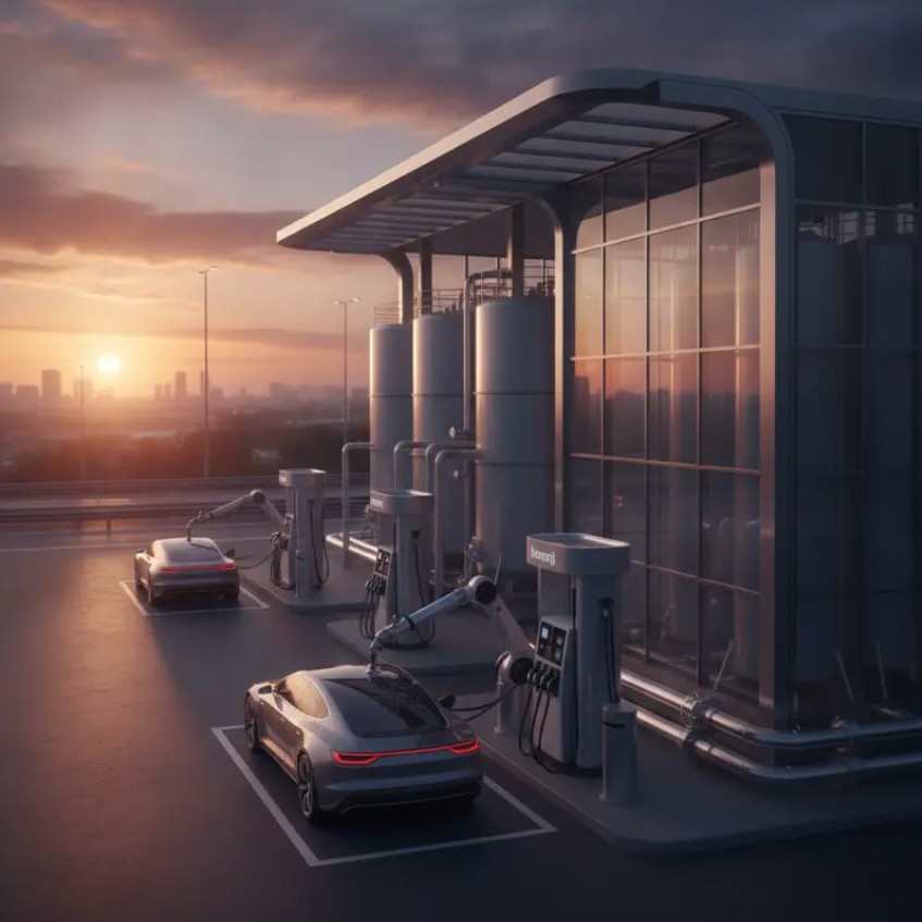
Hydrogen Refueling Station


Understanding the Importance of Quality Components in Hydrogen Refueling Stations

When considering hydrogen refueling stations, the quality of components is vital. Quality components ensure safety and efficiency. A reliable fueling station needs valves, pumps, and compressors that can withstand high pressure and corrosive environments. Subpar materials can lead to failures. This could cause leaks, posing serious safety risks.


Experience is essential in selecting suppliers. Examine their track record in the industry. A company with a history of durable products is worth consideration. Ask for case studies or references. Review their testing processes. Certifications and quality control measures offer insights into their commitment to excellence.


In hydrogen fueling technology, innovation is constant. Not all companies adapt quickly. Scrutinize their research and development efforts. A company that invests in new technologies is more likely to provide better solutions. Lastly, trust your instincts. If a proposal seems too good to be true, dig deeper. Quality should be non-negotiable in this crucial industry.

How to Choose High Quality Hydrogen Refueling Station Components Company?

Component Type Quality Rating (1-5) Material Used Compliance Standards Warranty Period
Compression Unit 4 Aluminum Alloy ISO 9001 5 Years
Storage Tank 5 Carbon Steel ASME 10 Years
Dispenser 3 Stainless Steel UL Listed 3 Years
Control System 4 Polycarbonate CE Mark 5 Years
Piping System 5 High-Density Polyethylene DNV GL 8 Years


Key Factors to Consider When Selecting Component Suppliers

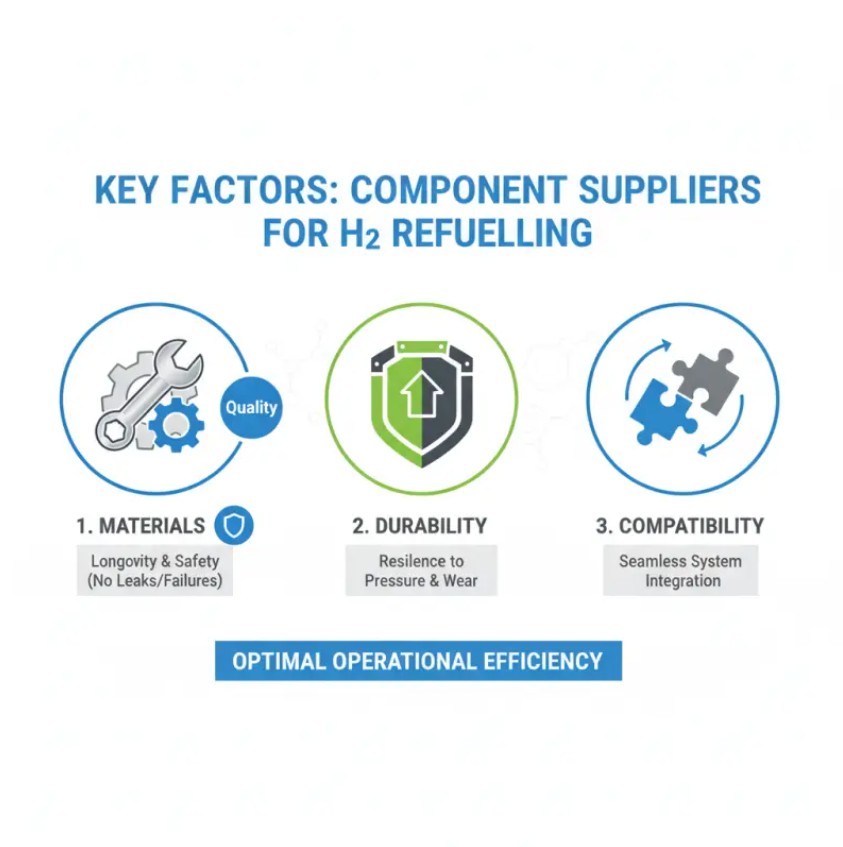
Hydrogen Refueling StationChoosing the right components for hydrogen refueling stations is vital for operational efficiency. Factors such as materials, durability, and compatibility matter significantly. Quality materials contribute to the longevity of the station. They ensure safety, preventing leaks or failures.


Evaluate the suppliers' experience in the hydrogen sector. A company with extensive experience understands industry challenges. They can provide tailored solutions that enhance performance. Communication also plays a crucial role. Frequent dialogue fosters trust and transparency. It allows for smoother project execution.


Certifications and industry standards are non-negotiable. Reliable suppliers adhere to safety regulations. However, not all certifications guarantee quality. Conduct thorough research to understand their significance. Talk to industry experts for insights. Additionally, observe their customer service. A quick response to inquiries indicates commitment to client satisfaction. Don't overlook these elements when making your choice.


Evaluating Supplier Experience and Reputation in the Hydrogen Industry

In the hydrogen industry, supplier experience plays a crucial role. A company with a long history of successful projects often indicates reliability and expertise. Look for suppliers who have worked with various clients and can demonstrate a range of successful installations. Their experience can reflect their understanding of industry standards and regulations, essential for ensuring safety and efficiency in your hydrogen refueling station.

When evaluating a supplier's reputation, customer reviews and industry feedback are invaluable. Seek out testimonials from past clients. Positive feedback can provide insight into the supplier's reliability and product quality. However, be mindful of biased reviews and look for patterns in feedback. These patterns can reveal strengths and weaknesses.

Tips: Always conduct a background check on potential suppliers. This research can highlight their influence in the industry. Consider their partnerships and collaborations as signs of trust. Moreover, don't hesitate to engage in conversations with previous clients. Understanding their experiences can lead you to better decisions. Making informed choices means actively seeking information, not just relying on surface-level data. This approach can save you from costly mistakes in the future.


Assessing Technical Specifications and Compliance Standards

When selecting a company for hydrogen refueling station components, it's vital to assess technical specifications. Look for detailed documentation that outlines material quality and safety protocols. Important factors include durability, pressure ratings, and compatibility. These details ensure that components can withstand the rigorous demands of hydrogen fueling.


Compliance with industry standards is another critical factor. Check if the company adheres to recognized safety and performance standards. Verification of certifications, such as those from regulatory bodies, is essential. This practice not only boosts confidence but also assures that components are reliable.


Sometimes, companies may present elaborate specifications. However, clarity and transparency are often overlooked. Be cautious of overly complex documents. Engage with experts to understand what these specifications entail. Ask questions to eliminate any doubts. Understanding how a component performs under various conditions is crucial for long-term reliability.


Comparing Pricing and Value for High-Quality Components

Selecting high-quality components for hydrogen refueling stations is crucial. The primary focus should be on balancing pricing with value. Quality often correlates with price, but it’s essential to do your research. Component longevity can save costs over time.

Tips: Consider maintenance costs and component reliability. Cheaper components may require more frequent replacements. Evaluate warranties carefully. A longer warranty often indicates confidence in product durability.

Understand vendor reputation through industry evaluations. Reliable suppliers often have industry certifications. These certifications reflect their adherence to quality standards. However, watch out for overly optimistic reviews; they may lack authenticity.

Gather quotes from multiple suppliers. This helps in comparing features and prices. Sometimes, a higher initial cost can lead to better performance and efficiency. Analyze each quote in detail. Don’t overlook the fine print, as it can reveal hidden costs or conditions.


Importance of After-Sales Support and Maintenance Services

When selecting a high-quality hydrogen refueling station components company, after-sales support and maintenance services are crucial. A well-supported component can ensure longevity and efficiency. According to recent industry reports, maintenance-related issues account for 35% of operational downtimes in hydrogen stations. This data highlights the need for reliable service agreements.

Tip: Always assess the maintenance services offered before making a decision. A company that provides timely support can save you costs in the long run.

Having access to trained technicians can prevent unexpected failures. In a sector where downtime can impact refueling capabilities, professional support gives peace of mind. The lack of proper services can lead not only to financial losses but also to reputational damage. Companies should ensure that training sessions for staff are included in their contracts.

Tip: Review customer feedback on after-sales support. A company with a strong track record will usually have testimonials showcasing their reliability.

Your choice matters. The right after-sales support can make a difference in operational efficiency. Yet, many organizations overlook this aspect, risking expensive repairs and delays. It’s essential to prioritize this element to safeguard investments in hydrogen technology.


Networking and Gathering Recommendations from Industry Professionals

When selecting a high-quality hydrogen refueling station components company, networking is essential. Industry professionals can provide valuable insights. According to a recent report from the Hydrogen Council, over 50% of industry stakeholders rely on recommendations from peer networks. Engaging in these networks can help you identify trusted suppliers.

Building relationships with professionals at trade shows or conferences allows for firsthand insights. Conversations often reveal which companies consistently deliver quality products. Moreover, you can gain information about industry trends that impact component quality. A survey found that 70% of professionals feel more confident in their choices when they have a supportive network.

Tip: Attend industry events to connect with experts. Your network can help navigate challenges in selecting components. Always ask for specific examples of successful projects. This provides a clearer picture of a company’s capabilities.

Regular discussions with your network are crucial. They can highlight red flags about potential suppliers. Consider creating a dedicated forum or group to share experiences. Transparency within your network encourages learning and improvement, leading to better decision-making in your component choices.


Conclusion

Choosing high-quality Hydrogen Refueling Station Components is crucial for ensuring the efficiency and safety of hydrogen fuel infrastructure. The importance of quality components cannot be overstated, as they directly impact the performance and longevity of the refueling stations. When selecting component suppliers, it's essential to consider key factors such as their experience and reputation in the hydrogen industry, along with their commitment to adhering to technical specifications and compliance standards.

Additionally, pricing should align with the overall value offered, where high-quality components can justify a higher initial investment through improved reliability and efficiency. After-sales support and maintenance services also play a vital role in sustaining operations. Networking with industry professionals and gathering recommendations can further guide in selecting the best suppliers, ensuring that all components meet the rigorous demands of the hydrogen refueling sector.


FAQ

Why is supplier experience important in the hydrogen industry?

Supplier experience indicates reliability and expertise, essential for successful installations.


How can I evaluate a supplier's reputation?

Look for customer reviews and industry feedback, but be cautious of biased opinions.


What should I do to ensure informed decision-making?

Conduct background checks and engage with previous clients to gather insights.


How do I balance pricing and value for components?

Research the quality of components as good longevity can reduce costs over time.


What maintenance considerations should I evaluate?

Cheaper components may have higher maintenance requirements and need more replacements.


How should I view warranties for components?

Longer warranties often indicate greater confidence in product durability and reliability.


What role do industry certifications play?

Certifications reflect adherence to quality standards and enhance supplier credibility.


How can I effectively compare supplier quotes?

Gather quotes from multiple suppliers and analyze features and prices in detail.


What common pitfalls should I avoid when evaluating suppliers?

Watch out for overly optimistic reviews that may not reflect genuine experiences.


How important is supplier collaboration in assessing trust?

Partnerships and collaborations can indicate a supplier's influence and reliability in the industry.


Continue
How to Determine RO Membrane Replacement Criteria and One-Stop Replacement Solutions?

According to the International Desalination Association (IDRA) Desalination & Reuse Handbook (2024–2025), there are currently approximately 23,000 seawater desalination plants worldwide, with a total capacity of 98.98 million m³/day, meeting the water needs of about 300 million people. Other industry data shows that in 2022, the global number of desalination plants had already reached 22,757. Reverse osmosis (RO) technology dominates the sector, accounting for 75% of the global desalination market in 2025. Beyond seawater desalination, the stock of membrane-based water treatment projects in industrial pure water, water reuse, and municipal water treatment is even larger. The global RO equipment market is expected to exceed US$12 billion in 2025. The total number of MBR membrane bioreactor projects worldwide has surpassed 3,400, nearly doubling since 2020.


Currently, global water treatment projects are entering a centralized operation and maintenance phase following large-scale commissioning. The period from 2018 to 2021 saw a peak in the installation of internationally branded RO membranes (Dow, Hydranautics, Toray, Saehan, etc.), with a large number of projects being completed and put into operation during this time. Taking the East Asian market as an example, the design life of internationally branded RO membranes is typically 3–5 years, provided that the feed water quality meets standards (SDI ≤ 3, residual chlorine < 0.1 mg/L, etc.). In industrial applications, membrane elements are generally replaced every 1–2 years. For water treatment projects with a capacity of over 10,000 tons per day, membrane replacement is required every 3–5 years. Some coastal regions in China have already entered a large-scale membrane replacement cycle. The Middle East, Europe, and the Americas are also facing similar concentrated replacement demand.


Based on comprehensive estimates, RO membrane projects using international brands installed between 2018 and 2021 have now fully entered the replacement window. These projects cover both seawater desalination and industrial/municipal sectors.


Seawater desalination sector: Among approximately 23,000 seawater desalination plants worldwide, RO technology accounts for 75%, meaning that more than 17,000 plants are equipped with RO membrane systems. Among these, RO desalination projects that were newly built or expanded between 2018 and 2021 are now entering a concentrated membrane replacement cycle.


Industrial and municipal sectors: Tens of thousands of RO systems worldwide for industrial pure water, water reuse, and municipal water treatment are also facing replacement demand.


According to industry research, approximately one-fifth of membrane water treatment users globally face the need for membrane retirement and replacement each year. Given the concentrated peak installations from 2018–2021, the proportion of projects entering replacement cycles in 2025–2026 is expected to far exceed this average, with some regions (such as coastal China) already clearly in a "large-scale membrane replacement cycle."


The global membrane system replacement service market reached US$18.74 billion in 2025, a year-on-year increase of 9.2%. The membrane system retrofitting and upgrade market was valued at US$1.93 billion, with an expected compound annual growth rate of 8%. Other studies estimate that more than 2 million RO membranes will be scrapped globally each year by 2025 – these figures indirectly confirm the enormous scale of replacement demand.


Behind this large-scale replacement demand lies the core pain points described in this article: high barriers to original equipment manufacturer (OEM) RO membrane maintenance, OEM parts monopolies, long cross-border replacement lead times, and persistently high long-term operation and maintenance costs. The world's top five membrane suppliers collectively hold a 71.5% market share, and this highly concentrated supply structure exacerbates the operational difficulties faced by end users. In 2025, approximately 41% of replacement service contracts have shifted to models such as "pay-per-volume treated" or "asset performance guarantees," reflecting the market's urgent need for cost-effective operation and maintenance solutions.


Compared with generic compatible membrane elements, original imported membranes have highly exclusive maintenance and replacement requirements, with numerous operational restrictions:


Closed-loop membrane fault repair with extremely low on-site feasibility:International-brand polyamide RO membranes have proprietary coating, adhesive sealing processes, and internal structures that are fully enclosed and protected by the original manufacturer. Standard global cleaning chemicals and off-line refurbishment equipment are not compatible with the original membrane structure, making routine fault repair extremely difficult:


(1) Limited restoration of scaling and biofouling:


Under conditions of high-hardness surface water, coastal high-salinity raw water, or biochemical reuse wastewater, the membrane surface is highly susceptible to biological slime, inorganic scale, colloids, and oil fouling. Original brand proprietary cleaning chemicals are priced at a premium, with high local procurement costs overseas. If third-party compliant cleaning agents are used, they can easily damage the proprietary anti-fouling coating on the membrane surface, resulting in permanent loss of salt rejection. Measured operational data shows that after non-OEM compliant cleaning, the salt rejection of original membranes can drop from the standard 99.4% to below 85%, rendering them essentially useless.


(2) Physical damage cannot be repaired through component replacement:


Water hammer, pretreatment filtration failure, scratches on the membrane surface from hard particulates, and aging/leakage of end seals are common hardware failures for original imported membranes. All major international brands use integrated sealed packaging processes. The membrane leaf, internal feed spacer, end adapters, and pressure end caps cannot be separately disassembled and replaced. The OEM only provides complete element replacement services – even for minor end damage or seal failures, the entire element must be scrapped and replaced, resulting in very low fault tolerance for repairs.


(3) Chemical corrosion repair requires factory return:


Original imported membranes have a fixed pH tolerance range with low fault tolerance. On-site non-standard acid or alkaline cleaning can cause membrane layer swelling, delamination, or rupture. Local third-party maintenance providers overseas do not have the restoration techniques – the only option is to return the membrane to the OEM's overseas factory for repair. The round-trip logistics and inspection/repair timeline takes 2–3 months, directly causing prolonged system shutdowns at the plant.

When any of the following types of irreversible faults occur in membrane elements, and performance cannot be restored through off-line chemical cleaning or pretreatment optimization alone, complete membrane element replacement is recommended. The criteria fall into three categories: performance degradation, physical structural damage, and operational economics.


(I) Continuous performance deterioration with no recovery after cleaning


Significant salt rejection decline: After correction under standard conditions (25°C, rated operating pressure, fixed recovery rate), salt rejection drops by more than 10%–15% from the initial value of new membranes, with product water TDS and conductivity exceeding limits for extended periods. After 2–3 rounds of standard acid, alkaline, and biological cleaning, salt rejection cannot be restored to the acceptable production range (for conventional industrial membranes, salt rejection below 85% generally renders them useless).

Irreversible permeate flux decline: Under the same operating parameters, system permeate flow drops by 15%–20% compared to new membranes. After excluding external factors such as cartridge filter blockage, low feed water temperature, or insufficient pressure, flow may temporarily recover after cleaning but quickly declines again – indicating compaction of the membrane active layer and permanent blockage of internal flow channels.

Persistent high differential pressure: The inter-vessel differential pressure or overall system differential pressure increases by more than 50% compared to new membranes, resulting in significantly higher energy consumption due to frequent high-pressure operation. After cleaning, the pressure drop reduction is less than 30%, meaning that inorganic scale, colloids, and biofilms have become deeply embedded in the membrane's internal feed spacer layer and cannot be thoroughly removed.

Loss of cleaning frequency control: Routine cleaning intervals that were originally 3–6 months are shortened to monthly or even bi-weekly chemical cleaning. The escalating costs of chemicals, labor, and downtime make long-term operation economically unsustainable.


(II) Irreversible physical/chemical damage with no possibility of repair

Membrane surface scratched by hard particulates, oxidation/hydrolysis, or acid/alkaline corrosion leading to delamination, resulting in persistent turbidity and particulate contamination in the product water. Center tube fracture, membrane roll deformation (telescoping), or seal leakage that cannot be individually repaired. Permanent destruction of the polyamide active layer due to prolonged chlorine exposure exceeding limits or extreme pH operation – no recovery process exists.


(III) Preventive replacement conditions (to avoid unplanned shutdowns)

Membrane elements have been in operation for 3–5 years (5–8 years for seawater desalination membranes), reaching their design service life, with performance entering a rapid decline phase. The original imported brand model has been globally discontinued, with no OEM spare parts or technical support available, making future faults unrepairable.

For older systems with frequent individual membrane failures, partial replacement with mixed new and old membranes can cause hydraulic imbalance, accelerating the scrapping of the entire membrane train. Batch replacement of the entire set is recommended. For overseas installed base of imported membranes from Dow, Hydranautics, Toray, Saehan, and other brands, our company provides a full one-stop service covering pre-sales diagnostics, membrane supply, long-term maintenance, and system retrofitting – meeting the full lifecycle needs of overseas projects:


1. Pre-sales technical diagnostics and solution customization services

●Remote comprehensive water quality testing (TDS, hardness, COD, ammonia nitrogen, turbidity, SDI), combined with on-site operating differential pressure, permeate flow, and salt rejection data, to issue a membrane life assessment report.

●Equivalent replacement selection for old imported membrane models: match replacement membranes of the same size, flow rate, and salt rejection specifications based on the original membrane dimensions, distinguishing between brackish water, anti-fouling, seawater desalination, and low-pressure specialty membranes, providing a side-by-side performance comparison.

●Project operating condition optimization: adjust recovery rate, chemical dosing, and pretreatment processes to extend the service life of existing imported membranes and defer replacement investment.


2. Global supply of full-specification membrane elements

●Our company's stock of equivalent replacement membranes is available off-the-shelf.

●Standard 4040/8040 universal specifications are maintained in inventory. For specialty or discontinued non-standard models, custom production can be arranged. Support for full-container cross-border export, including customs declaration, shipping, and complete export documentation.

●Simultaneous supply of all supporting consumables: FRP vessel end caps, O-rings, connectors, specialty cleaning chemicals, antiscalants, and cartridge filter elements – enabling one-stop consumables procurement.


3. Specialized membrane cleaning, maintenance, and life-extension services

●Equipped with large-scale off-line membrane cleaning equipment for segmented chemical cleaning and physical flushing of repairable imported membranes to remove inorganic scale, biological slime, and colloidal fouling.

●Provide remote 24/7 technical support, with online guidance for overseas operation and maintenance personnel to independently perform routine flushing and simple chemical cleaning procedures.


4. Long-term after-sales and technical training services

●Global membrane element warranty service, including cross-border fault replacement and technical claims for performance abnormalities.

●Online hands-on training for overseas O&M teams: complete standardized courses on membrane disassembly/assembly, fault diagnosis, chemical cleaning, and routine operation management.

●Long-term O&M outsourcing services: annual maintenance agreements covering regular consumables supply, on-site inspections, and annual operation optimization reports.


FAQ:

Who are we?
We are based in Anhui, China, start from 2011,sell to Southeast Asia,North America,Eastern Europe,South Asia.


Can you customize the rated power or voltage?
Yes, customizing products is acceptable.


Can your company provide whole system(fuel cell, Hydrogen production, hydrogen storage, hydrogen supply system)?
Yes, we can provide necessary accessories accordingly.


Why should you buy from us not from other suppliers?
We have an experienced professional technical research and development team. Control system matching ability/R&D and quality control ability. Price advantage brought by supply chain integration capabilities.
 

Continue
Measures to Address Abnormal Voltage Faults in Chlor-Alkali Electrolyzers

The electrolyzer is the core and critical equipment in chlor-alkali chemical production. It utilizes ion-exchange membrane electrolysis technology to electrolyze brine, producing key products such as caustic soda, chlorine gas, and hydrogen gas. Its operational stability and safety directly determine the production capacity, energy consumption, and product quality of the entire production line. Under long-term continuous production conditions, influenced by multiple factors such as medium corrosion, material impurities, operational parameter fluctuations, equipment aging, and improper maintenance, abnormal electrolyzer voltage not only affects the normal operation and equipment lifespan of the electrolyzer but may also trigger safety hazards such as gas crossover and pressure imbalance.


1. Core Causes of Abnormal Electrolyzer Voltage


1.1 Substandard Brine Purification Water Quality

When the quality of the brine purification process fails to meet standards, magnesium ion content and suspended solids content may exceed limits. These impurities enter the electrolyzer along with the purified brine, forming deposits on the surface of the ion-exchange membrane and blocking the membrane pores, resulting in degraded ion-exchange performance. The increase in membrane resistance directly leads to elevated cell voltage.


1.2 Imbalanced Production Process Parameter Control

If the catholyte caustic soda concentration of the electrolyzer is controlled well above the process standard value, the excessive osmotic pressure of the caustic solution will increase the resistance of the ion-exchange membrane. If the operating temperature of the electrolyzer is controlled too low, the ion migration rate of the electrolyte will decrease, leading to increased ohmic voltage drop within the electrolyzer. If the pressure differential between the anode and cathode chambers is unreasonably controlled, resulting in reverse pressure differentials or excessive fluctuation amplitude, the membrane-to-electrode contact tightness will decrease, increasing membrane resistance. If the acidity of the anolyte is controlled too high, the corrosion process of the anode will accelerate, which also indirectly causes the cell voltage to rise.


1.3 Natural Aging of the Ion-Exchange Membrane

During long-term operation, the ion-exchange membrane is continuously subjected to multiple effects including chemical medium corrosion, electrolyte erosion and wear, and impurity adsorption and blockage, leading to natural aging phenomena. Its ion-exchange capacity and permeation stability gradually decline, and the membrane resistance steadily increases with operating time, ultimately causing a slow and persistent rise in cell voltage. This is a typical normalized fault trigger for equipment under long-term operation.


1.4 Non-Standard Equipment Load Adjustments

Excessive adjustment amplitude and excessively rapid changes in the operating current of the electrolyzer will lead to uneven electrolyte distribution within the electrolyzer, causing a mismatch between ion migration rate and current intensity, resulting in abnormal cell voltage elevation. Additionally, after increasing the operating load of the electrolyzer, if the process parameters such as caustic soda concentration, anolyte and catholyte circulation volume, and electrolyzer temperature are not promptly optimized and adjusted accordingly, this will also lead to elevated cell voltage.


2. Remedial Measures


2.1 Comprehensive Inspection of Equipment Operating Conditions

Conduct a comprehensive inspection of the electrolyzer's operating status, with a focus on confirming whether the conductive busbar joints of the electrodes exhibit overheating or excessive contact resistance, whether the indications of relevant instruments are normal and free from deviations, and progressively narrow down the scope of fault investigation.


2.2 Strict Control of Brine Water Quality

Re-sample and analyze the quality of the secondary purified brine, focusing on testing whether key indicators such as calcium and magnesium ion content, suspended solids content, and pH value meet the process standard requirements. If any exceedances are found, adjust the dosage of purification agents, switch to the standby chelating resin tower, and if necessary, reduce the operating load of the electrolysis process to decrease the impurity load on the ion-exchange membrane and mitigate the extent of cell voltage elevation.


2.3 Regulation of Process Parameters

Appropriately reduce the operating current of the electrolyzer to decrease the electrochemical reaction intensity; moderately raise the operating temperature of the electrolyzer to improve the ion migration performance of the electrolyte; precisely adjust the concentration of the catholyte caustic soda to control it within the process standard range; readjust the pressure differential between the anode and cathode chambers of the electrolyzer to comply with technical standard requirements; suspend the addition of hydrochloric acid to the anode chamber to reduce the acidity load of the anolyte and decrease membrane resistance.


Abnormal electrolyzer voltage is a comprehensive manifestation of multi-dimensional issues encompassing water quality management, process parameters, equipment status, and operational standards. In daily production, source prevention and control should be the core, combined with precision maintenance, standardized operations, and real-time inspections to build a comprehensive prevention and control system, proactively resolving various triggering hazards and reducing the occurrence of abnormal voltage faults.

Continue
Top China Ammonia Synthesis Equipment Suppliers You Can Trust?

You know, there's never been a bigger buzz around finding efficient ways to produce ammonia. Especially in China, where the industry’s changing so quickly, staying ahead means finding the right partner. That’s where China Leading Ammonia Synthesis Equipment Supplier comes in—offering cutting-edge solutions to keep up with all that demand.

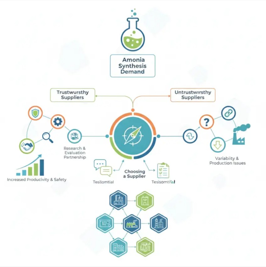
Now, lots of companies claim they have the best ammonia synthesis equipment, but honestly, not all of them really deliver. You’ve got to look for suppliers with real experience and some serious know-how in this niche. Taking the time to check out their track record is key, because the quality can really vary and that can impact your entire operation.

When you're trying to pick a supplier, don’t just go with the first one you find—think about their reputation, read some client stories, you know, get a feel for how they've handled things. The right equipment can boost your productivity and keep things safe, but it’s super important not to rush—make sure you really understand what your project needs before making a decision. After all, every choice you make can seriously influence how well everything turns out down the line.

Ammonia Synthesis Equipment


Overview of Ammonia Synthesis Equipment in China

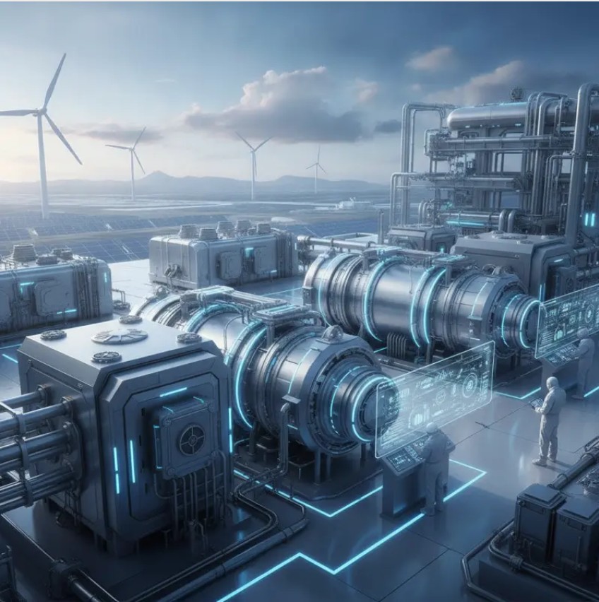
Ammonia synthesis equipment plays a crucial role in industrial production. It is essential for creating fertilizers, explosives, and various chemicals. China has emerged as a leading player in this sector. The demand for high-quality ammonia synthesis technology continues to climb.

When considering equipment, several factors come into play. Efficiency, durability, and scalability are vital. Many suppliers in China offer advanced solutions. Some focus on innovation, while others prioritize cost-effectiveness. It's important to evaluate each supplier's reputation and expertise. Quality control is another key aspect. Flaws in equipment can lead to significant production losses.

Potential buyers should conduct thorough research. Understanding the specifications and performance of different equipment is crucial. Engaging with suppliers for consultations can provide valuable insights. Be aware that not all suppliers meet every requirement. A well-informed decision often involves examining multiple options.


Key Manufacturers in the Chinese Ammonia Synthesis Industry

In the rapidly evolving field of ammonia synthesis, China's manufacturers stand out for their innovative solutions and dedicated expertise. Key players in this industry focus on efficiency and sustainability. This approach reflects a growing emphasis on reducing environmental impacts while meeting global demand. Experts frequently note that the integration of advanced technologies is crucial for maintaining competitiveness in this sector.

These manufacturers are known for producing high-quality ammonia synthesis equipment. They leverage their experience to develop systems that comply with international standards. However, the industry's rapid pace can sometimes lead to challenges in quality control. Some manufacturers struggle with consistency in product offerings. This aspect is crucial for buyers seeking reliable partners in the ammonia synthesis market.

The ability to source materials locally also plays a significant role in production efficiency. Many suppliers are refining their processes to minimize waste and optimize resource use. Even with these advancements, there remains room for improvement in operational transparency. Potential buyers should consider these factors when evaluating top suppliers in China's ammonia synthesis landscape.


Market Share Analysis of Top Ammonia Equipment Suppliers

Ammonia Synthesis Equipment

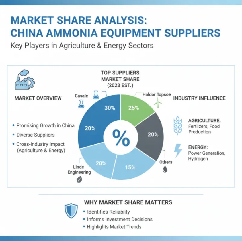
The market for ammonia synthesis equipment in China holds significant promise. A variety of suppliers are competing for attention. Their influence is felt across multiple industries, including agriculture and energy. Understanding market share helps in identifying which suppliers offer the most reliability.

In this bustling sector, some companies dominate. They have invested heavily in research and development. This results in innovative technologies that improve efficiency. However, not all suppliers deliver the same level of quality. Some have faced challenges related to production and customer service. Potential buyers should assess these aspects closely.

Market dynamics can shift rapidly. Emerging suppliers may disrupt the landscape with fresh approaches. Buyers should remain vigilant. Evaluating supplier reliability requires a keen eye on their track record. It’s crucial to gather insights from previous clients and industry reports. This ensures informed decisions in choosing a partner for ammonia synthesis equipment.


Technological Innovations in Ammonia Production Equipment

Technological innovations are transforming ammonia production equipment. Recent advancements enhance efficiency and reduce energy consumption. New catalysts are being developed to maximize output, allowing for greener production processes. These innovations not only support environmental sustainability but also address the growing global demand for ammonia.


Furthermore, automation is playing a crucial role in modern ammonia synthesis. Smart systems enable real-time monitoring and control. This reduces the risk of human error and improves operational safety. However, integrating such technologies can be challenging for some manufacturers, causing delays in implementation.


Investment in research and development is essential. It helps companies stay competitive while fostering new ideas. But the path to innovation is not without obstacles. Many firms struggle to balance cost with the desire for advanced technology. Ultimately, embracing change is necessary for success in the ammonia production industry.


Quality Standards and Certifications for Ammonia Synthesis Equipment

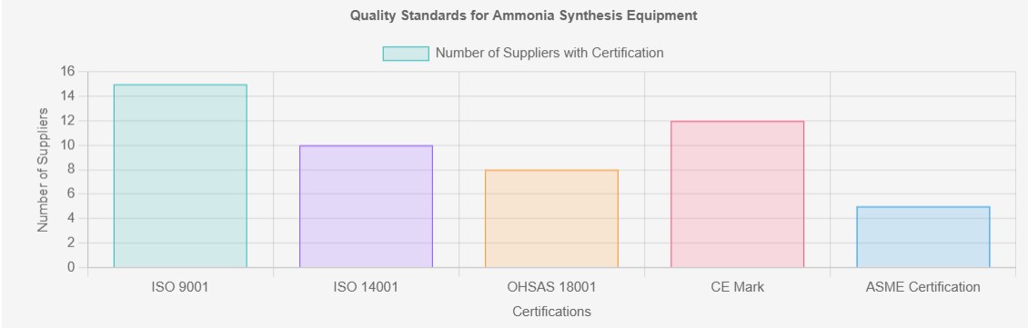
Quality standards for ammonia synthesis equipment are crucial. They ensure the production process is efficient and safe. Equipment should meet specific international standards. Certifications like ISO and CE are essential. They indicate that the equipment complies with global safety and quality benchmarks. Manufacturers must invest in these certifications to gain trust.

Testing is a vital part of maintaining quality. Regular inspections can help identify potential issues. Even with high-quality equipment, there can be hidden flaws. Performance validation is necessary. It makes the operation more reliable. Documentation during the testing phase should be meticulous.

Not all suppliers meet these rigorous standards. Some may promise high quality but deliver subpar equipment. Conducting thorough research is crucial before selecting a supplier. Peer reviews and industry feedback can provide insights. Relying solely on marketing claims is risky. A proactive approach will lead to better decisions.


Top China Ammonia Synthesis Equipment Suppliers - Quality Standards and Certifications

Ammonia Synthesis Equipment


Cost Comparison of Leading Ammonia Equipment Suppliers in China

In the competitive market of ammonia synthesis equipment, understanding cost structures is essential for buyers. Recent industry analyses indicate that equipment prices can vary significantly. For instance, basic ammonia synthesis units range from $800,000 to $2 million, depending on capacity and technology. These variations highlight the importance of careful supplier assessment.

A critical factor is operational efficiency. This can affect long-term costs. Some suppliers report energy consumption rates of 7-10 GJ per ton of ammonia produced. Companies that employ advanced catalytic processes often have lower operating costs. However, the initial investment in such technology might be higher. These factors create a complex decision matrix for buyers, emphasizing the importance of evaluating total cost of ownership, not just upfront expenses.

Additionally, reliability and support services matter. Suppliers that offer better warranties and maintenance packages may justify higher costs. Industry benchmarks suggest that unscheduled downtime can cost producers nearly $28,000 per hour. Therefore, investing in dependable equipment can save significant money over time. This intricate landscape illustrates the need for thorough research and expert consultations when selecting ammonia synthesis equipment suppliers in China.


The future of China's ammonia synthesis equipment market is evolving rapidly. Emerging technologies drive efficiencies and sustainability in ammonia production. Industry experts predict a shift towards advanced catalysts that enhance reaction speeds and reduce energy consumption.

Furthermore, environmental concerns push manufacturers to innovate. There's a growing emphasis on low-emission technologies. Companies are exploring renewable energy options to power production processes. This shift may require significant investment but could lead to a more sustainable industry.

Collaborations among research institutions and manufacturers are pivotal. The exchange of ideas can catalyze innovation. Despite the potential, challenges abound in scaling new technologies. Companies must navigate regulatory landscapes and market demands, prompting reflection on their strategies. Balancing innovation with practicality will be crucial for future success.


Conclusion

The article provides a comprehensive overview of ammonia synthesis equipment in China, highlighting key manufacturers and their market share. It discusses the technological innovations that are shaping the ammonia production industry and outlines the quality standards and certifications essential for equipment reliability. A cost comparison among leading suppliers reveals significant insights into pricing strategies in the competitive landscape.

As the demand for ammonia continues to rise, understanding the future trends in China’s ammonia synthesis equipment market is crucial. The analysis emphasizes the role of China leading ammonia synthesis equipment suppliers in driving advancements and ensuring quality, positioning them as key players in meeting both domestic and global ammonia production needs.


FAQS

Why are quality standards important for ammonia synthesis equipment?

They ensure safe and efficient production processes.


What certifications should ammonia synthesis equipment have?

ISO and CE certifications indicate compliance with international safety standards.


How do manufacturers maintain quality in their products?

Regular testing and inspections help identify potential issues and ensure reliability.


What challenges do manufacturers face in quality control?

Some struggle with consistency in product offerings, leading to potential reliability issues.


How can buyers assess the reliability of suppliers?

Conduct thorough research and check peer reviews for insights about supplier performance.


Why is operational transparency important in production?

It helps buyers evaluate the efficiency and accountability of suppliers in the industry.


What role does local sourcing play in ammonia production?

It can enhance production efficiency by minimizing waste and optimizing resources.


Are all manufacturers compliant with quality standards?

Not all suppliers meet rigorous standards, leading to risks in product quality.


How can hidden flaws affect equipment performance?

Even high-quality equipment can have issues that impact reliability during operation.


Is relying solely on marketing claims a good strategy?

No, it is risky. A proactive approach is necessary for informed decision-making.


Continue
Top Famous Best Hydrogen Compression Modules Manufacturer Revealed?

Lately, there's been a noticeable spike in the global demand for Hydrogen Compression Modules, mainly because everyone’s now talking about clean energy solutions. I came across a report from MarketsandMarkets that suggests the hydrogen compression market might hit around $XX billion by 2025, with a pretty healthy growth rate of XX%. This really shows how much people are starting to see hydrogen as a key player in our energy future.

Dr. Emily Tran, who’s honestly one of the top experts in hydrogen tech, mentioned that 'Hydrogen Compression Modules are absolutely critical for storing and moving energy efficiently.' I think that just highlights how important it is to have advanced compression tech as we build out the hydrogen economy. Big companies like Hydrogenics, Plug Power, and Nelson Global Products are really pushing the envelope here, but let’s be honest, there are still hurdles—like making sure these systems are reliable and affordable.

The whole hydrogen compression scene is changing pretty fast, but questions still pop up regarding whether we can really scale these solutions and how efficient they truly are. People involved in this space are working hard to troubleshoot these issues, and everyone’s waiting for some big breakthroughs that could totally shake up how we think about renewable energy and storage.

Hydrogen Compression Modules Manufacturer

Overview of Hydrogen Compression Modules and Their Importance

Hydrogen compression modules play a crucial role in the hydrogen supply chain. These modules ensure efficient transportation and storage of hydrogen gas, which is essential for various applications, including fuel cells and industrial processes. According to industry reports, the global hydrogen market is projected to reach $200 billion by 2025. This growth directly correlates with the increasing demand for effective hydrogen compression systems.

The importance of these modules lies in their ability to enhance safety and reduce energy consumption. Efficient compression can lead to significant cost savings. Data indicates that improving compression efficiency by just 10% can decrease operational costs by nearly 20%. Despite advancements, many systems still suffer from inefficiencies and technical challenges. For instance, achieving optimal pressure levels while minimizing energy use remains a complex task.

Furthermore, the reliability of these systems must continually be assessed. A study found that approximately 15% of hydrogen compressors experience mechanical failures within their first year. This statistic highlights the need for ongoing innovation and rigorous testing protocols in the industry. As the market expands, addressing these challenges will be vital for sustaining growth and enhancing the role of hydrogen as a clean energy source.


Key Technologies Used in Hydrogen Compression Modules

Hydrogen compression modules are crucial in the transition to cleaner energy. These modules facilitate the storage and transport of hydrogen, a key player in reducing carbon emissions. Advanced technologies are essential for optimizing efficiency and ensuring safety in these systems.

Key technologies include diaphragm compressors and ionic liquid-based systems. Diaphragm compressors offer high flexibility and low maintenance. They operate efficiently at varying pressures. Additionally, ionic liquids enhance the condensation process, significantly improving energy recovery rates. Reports indicate that hydrogen production could demand a compression capacity increase of up to 40% by 2030, demonstrating the pressing need for innovation in this sector.

Moreover, real-world applications reveal some challenges. For instance, energy losses during compression can reach 15-20%. This inefficiency prompts manufacturers to explore new designs and materials. Continuous improvement is necessary to meet the growing hydrogen demand. The industry must adapt, utilizing data-driven insights for future advancements to achieve optimal performance in hydrogen compression.


Leading Manufacturers of Hydrogen Compression Modules: A Comparative Analysis

Hydrogen Compression Modules

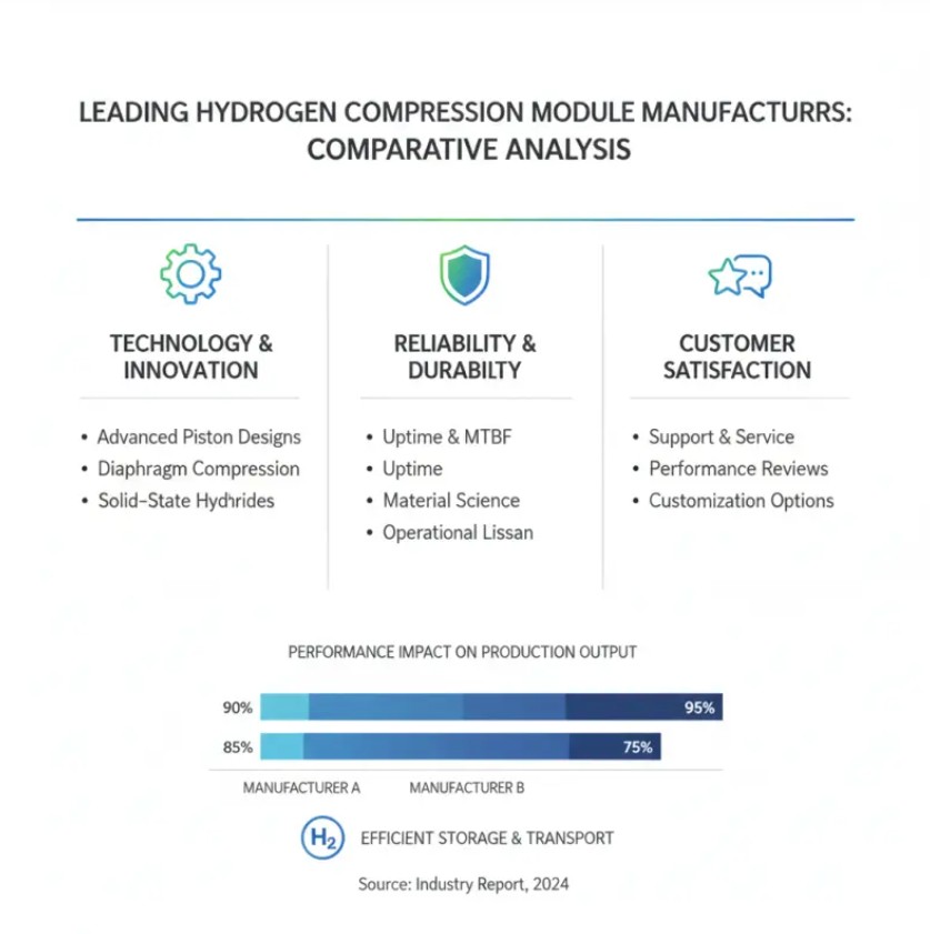
Hydrogen compression modules are essential in various industries. They ensure the safe and efficient storage and transportation of hydrogen. Leading manufacturers in this field are evaluated based on their technology, reliability, and customer feedback. Performance affects production output significantly.

Key players utilize advanced materials and innovative designs. This allows for high-pressure applications while maintaining safety standards. However, there are always challenges. Some manufacturers struggle with scalability, affecting their overall market influence. The ability to meet diverse customer needs is crucial for choosing the right module.

Furthermore, industry regulations influence manufacturing processes. Compliance is vital for operational credibility. Manufacturers need to adapt quickly to technological advancements as well. This ever-evolving landscape requires ongoing assessment and improvement. Continuous learning is important to address consumer demands and market changes.


Criteria for Evaluating the Best Hydrogen Compression Module Manufacturers

Hydrogen Compression Module Manufacturers

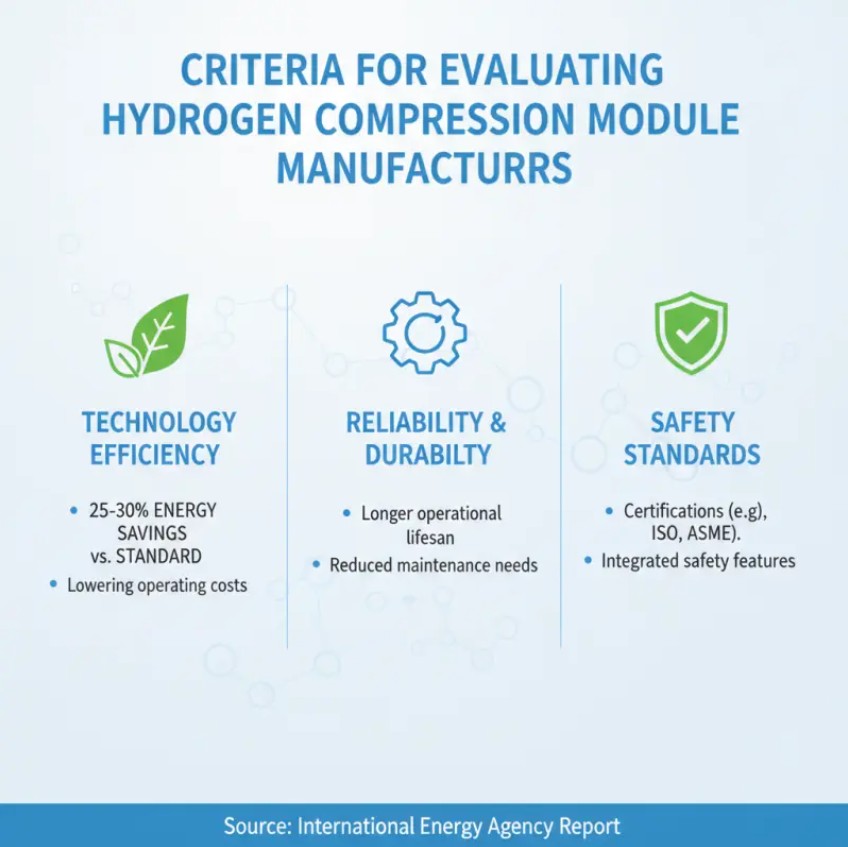
When evaluating hydrogen compression module manufacturers, several key criteria emerge as essential. The efficiency of the technology plays a pivotal role. A report by the International Energy Agency noted that optimal compression efficiency can lead to significant energy savings, improving the overall cost-effectiveness of hydrogen production. High-performance modules typically demonstrate a 25-30% reduction in energy consumption compared to standard options.

Another important factor is the reliability of the equipment. Manufacturers with proven track records in the industry often use advanced materials that enhance durability and reduce maintenance needs. A recent industry study revealed that less than 10% of high-reliability modules experienced significant downtime over five years. This indicates that quality engineering substantially impacts performance longevity.

Additionally, safety standards are crucial in selecting a manufacturer. The implementation of strict quality assurance measures can mitigate risks associated with hydrogen compression. However, not all suppliers adhere to equally rigorous evaluations. Reports indicate that manufacturers with ISO certification and consistent testing protocols are indeed more reputable. This underscores the importance of thorough vetting when assessing potential partners.


Hydrogen compression technology is advancing rapidly. Innovations are improving efficiency and sustainability. New modules are designed to reduce energy consumption and lower costs. Many manufacturers focus on enhancing durability and performance in demanding environments. This shift is crucial as industries move towards more eco-friendly solutions.

Recent trends highlight the integration of smart technologies. Artificial intelligence is being implemented to optimize operations. Data analytics can monitor performance in real-time, leading to proactive maintenance. However, reliance on these technologies can introduce vulnerabilities. A system malfunction could disrupt operations significantly.

Another emerging trend is modular design. This approach allows for flexibility and scalability. Manufacturers can customize systems based on user needs. Yet, this also raises questions about compatibility and standardization. As the market grows, establishing uniformity becomes increasingly complex. The innovations are exciting, but they require careful implementation to ensure reliability.


Case Studies: Successful Implementations of Top Manufacturers

Hydrogen compression modules play a crucial role in the energy transition. Various manufacturers have been making strides in this field. Examining real-world cases helps illuminate their success. These case studies showcase innovative approaches and practical applications in diverse settings.

One notable implementation involved a large renewable energy facility. Their hydrogen compression system optimized output and reduced operational costs. The design facilitated smooth integration with existing infrastructure. Challenges arose during the initial phase, but adjustments led to improved efficiency. This adaptability highlights the importance of resilience in technology deployment.

Another case featured an industrial application. The company sought to increase their hydrogen storage capacity. They chose a modular compression system that streamlined their processes. However, they encountered issues with supply chain dependencies. A deeper analysis revealed the need for local sourcing strategies. Such reflections drive continuous improvement in manufacturing practices.

These examples reflect a commitment to advancement in hydrogen technology. They show how strategic implementation can solve real challenges. Each story offers valuable lessons for future endeavors in this evolving market.


Future Prospects for Hydrogen Compression Modules in the Energy Sector

The energy sector is evolving, and hydrogen compression modules play a crucial role. These modules facilitate the efficient storage and transport of hydrogen. As countries seek cleaner energy sources, the demand for compressed hydrogen is rising.

Future prospects for hydrogen compression modules look promising. Experts predict significant investments in this area. Advancements in technology could lead to smaller, more efficient modules. However, challenges remain. For instance, ensuring safety during storage is a major concern. Industry stakeholders must prioritize research to address these issues.

Tips: When considering hydrogen compression solutions, evaluate the efficiency ratings. Understand the long-term operational costs versus initial investments. Safety certifications are vital in this evolving market. This ensures reliability and compliance in operations. Quality modules will significantly impact your energy strategy.


Conclusion

Hydrogen Compression Modules play a crucial role in the hydrogen supply chain, facilitating the efficient storage and transport of hydrogen in various applications. These modules utilize advanced technologies, including high-pressure compressors and innovative cooling systems, to enhance performance and reduce energy consumption. A comparative analysis of leading manufacturers highlights the varying approaches and solutions offered in this rapidly evolving industry.

Evaluating the best manufacturers involves examining criteria such as technology, efficiency, reliability, and customer support. Recent innovations emphasize sustainability, with trends focusing on enhancing the efficiency and scalability of hydrogen compression processes. Case studies of successful implementations underscore the practical effectiveness of top manufacturers, indicating a promising future for Hydrogen Compression Modules within the energy sector as demand for clean energy solutions continues to rise.


FAQS:

What is hydrogen compression technology?

 It is a method for storing and transporting hydrogen efficiently.


Why is efficiency important in hydrogen compression?

Higher efficiency reduces energy consumption and lower costs in operations.


What role does artificial intelligence play in this technology?

AI optimizes operations and enables real-time performance monitoring.


Are there risks associated with relying on smart technologies?

Yes, system malfunctions can disrupt operations and introduce vulnerabilities.


What is modular design in hydrogen compression?

It allows flexibility and scalability, enabling customization based on user needs.


Why is standardization challenging in the hydrogen market?

As more manufacturers enter the market, ensuring compatibility becomes complex.


What are future prospects for hydrogen compression modules?

Promising advancements may lead to smaller and more efficient modules.


What safety concerns exist with hydrogen storage?

Ensuring safety during storage is critical and requires ongoing research.


What should be considered when choosing hydrogen solutions?

Evaluate efficiency ratings, long-term costs, and essential safety certifications.


How do quality modules impact energy strategies?

They significantly affect operational reliability and overall effectiveness.


Continue
What Ions Can Electrodialysis Remove?

Electrodialysis (ED) is an independent membrane-based desalination pathway distinct from pressure-driven membrane technologies (RO/NF/UF/MF). Driven by an electric field, it achieves ion separation through the selective migration of ion exchange membranes, complementing rather than competing with RO.


The core component of ED is the membrane stack: between the anode and cathode, CEMs (cation exchange membranes, which only allow cations to pass) and AEMs (anion exchange membranes, which only allow anions to pass) are arranged alternately, forming alternating "diluate chambers" and "concentrate chambers." When saline feed water enters the diluate chamber, under the electric field: cations (Na⁺, Ca²⁺, Mg²⁺, K⁺, etc.) migrate toward the cathode, pass through the CEM into the adjacent concentrate chamber, but are blocked by the next AEM and retained in the concentrate chamber; anions (Cl⁻, SO₄²⁻, NO₃⁻, HCO₃⁻, etc.) migrate toward the anode, pass through the AEM into the adjacent concentrate chamber, but are blocked by the next CEM and retained in the concentrate chamber. The result: the ion concentration in the diluate chamber effluent is significantly reduced, while the concentrate chamber effluent is enriched with ions migrated from the diluate chamber. The entire process requires no phase change, no high pressure, and no chemicals.


What ions can electrodialysis remove?

The ion types, common sources, removal mechanisms, and engineering considerations are as follows:

Ion

Common Sources

Removal Mechanism and Engineering Considerations

Na⁺

Salt, seawater, brackish water, industrial wastewater

Monovalent cation with fast migration rate. A core removal target of ED — desalination rate depends on applied current density and number of membrane stack stages. Final effluent Na⁺ can be as low as 5–20 mg/L.

K⁺

Agricultural runoff, food processing wastewater

Chemical behavior highly similar to Na⁺; ED removal efficiency is nearly identical. In whey desalination, K⁺ is effectively removed together with Na⁺.

Fe³⁺/Fe²⁺

Acid mine drainage, groundwater

High retention rate for multivalent cations, but attention must be paid to Fe(OH)₃ precipitation clogging membrane pores. pH needs to be controlled in the acidic range before influent, or pre-oxidation precipitation removal is required.

NH₄⁺

Municipal wastewater, aquaculture wastewater, landfill leachate

Monovalent cation; removal rate depends on competing ion concentrations. NH₄⁺ removal is competitively inhibited in high Na⁺ environments. The form of ammonia nitrogen is pH-controlled (predominantly NH₄⁺ at pH<9, removable by ED; converts to NH₃ molecules at pH>10 → ED cannot remove).

Li⁺

Salt lake brine, lithium battery recycling

Monovalent small ion; faces competition when coexisting with large amounts of Mg²⁺. Requires selective ion exchange membranes or NF pretreatment to first separate Mg²⁺, then use ED to concentrate Li⁺.

NH₄⁺

Municipal wastewater, aquaculture wastewater, landfill leachate

Monovalent cation; removal rate depends on competing ion concentrations. NH₄⁺ removal is competitively inhibited in high Na⁺ environments. The form of ammonia nitrogen is pH-controlled (predominantly NH₄⁺ at pH<9, removable by ED; converts to NH₃ molecules at pH>10 → ED cannot remove).

Cl⁻

Salt, seawater, industrial wastewater

Fastest migration rate among anions. The “primary target anion” for ED desalination.

SO₄²⁻

Groundwater, mine drainage, industrial wastewater

Divalent anion → high charge density → strong electric field driving force → extremely high retention rate. One of the most efficiently removed targets by ED. However, CaSO₄ scaling risk in the concentrate chamber requires special control.

NO₃⁻

Agricultural runoff, fertilizer-contaminated groundwater

Moderate removal rate for monovalent anions. ED is an important technology for nitrate removal from drinking water — compared to RO, ED does not produce high-salinity concentrate and has a higher recovery rate (80–95%).

HCO₃⁻

Natural alkalinity (groundwater)

Removing HCO₃⁻ reduces the buffering capacity of water, leading to a decrease in effluent pH (due to CO₂ dissolution equilibrium shift). ED treatment of high-alkalinity water requires post-treatment pH adjustment.

F⁻

High-fluoride groundwater (endemic disease areas)

ED is one of the WHO-recommended technologies for fluoride removal from drinking water. Removal efficiency is significantly affected by competing ions (Cl⁻, SO₄²⁻) and pH.

Organic acid anions
(acetate, lactate, citrate)

Food fermentation broths, industrial wastewater

Organic ions have larger molecular volumes → higher migration resistance in membranes than inorganic small ions → lower removal rates. Polyvalent organic acids (e.g., citrate³⁻) have better removal rates than monovalent organic acids (e.g., acetate⁻).


However, it should be noted that electrodialysis systems are relatively sensitive to certain heavy metal ions, and the water quality entering the ED system has certain requirements. Therefore, pretreatment of the source wastewater is necessary to meet the influent standards. In terms of physical interception, mechanical filtration, ultrafiltration (UF), and cartridge filters are typically used to remove sediment, colloids, and other impurities, keeping suspended solids (SS) strictly at low levels. In terms of chemical and adsorption treatment, activated carbon filters are used to remove free chlorine with oxidative damaging effects, color, and some organic matter, and scale inhibitors are dosed or pH is adjusted based on water quality to prevent inorganic salt scaling. For hardness ions such as calcium and magnesium, as well as high-valence metal ions such as iron and manganese, deep removal through chemical softening or chelating resins is required to significantly reduce the scaling and poisoning burden on the membrane surfaces.


After the above pretreatment, the water quality entering the ED system must meet a series of core control indicators: suspended solids (SS) generally required below 1 mg/L; the sum of divalent and higher-valent cations prone to hydroxide precipitation, such as calcium, magnesium, iron, and zinc, must be <0.3 mg/L; and free chlorine must be reduced below the safety threshold of 0.5 mg/L. In addition, water temperature typically needs to be controlled between 5–40°C. In practical engineering applications, the combination of pretreatment processes (e.g., “pretreatment + softening + ED” or “pretreatment + RO + ED”) is flexibly configured based on raw water quality characteristics and final product water requirements to achieve efficient, long-cycle operation of the system.


FAQ:

1. What is the working principle of electrodialysis?

Driven by an electric field, it uses alternately arranged CEMs and AEMs to realize selective ion migration, to purify water and concentrate ions.


2. What are the advantages of electrodialysis compared with RO?

Electrodialysis requires no high pressure and no chemicals, features higher water recovery rate and no high-salinity concentrate production.


3. What water scenarios is electrodialysis suitable for?

It applies to seawater, brackish water, industrial wastewater, agricultural runoff, groundwater and salt lake brine treatment.

Continue
When Does the Ion-Exchange Membrane Electrolyzer in Chlor-Alkali Process Need Replacement? One-Stop Replacement Solutions

The ion-exchange membrane electrolyzer is the "heart" equipment of the membrane-based chlor-alkali process. It receives purified brine and produces three core products – caustic soda, chlorine gas, and hydrogen – through direct-current electrolysis. It directly determines the production capacity, energy consumption, product purity, and operational safety of the entire chlor-alkali production line. Compared with ordinary chemical equipment, ion-exchange membrane electrolyzers operate under more severe conditions, have highly monopolized spare parts, and require much higher maintenance thresholds. As early-stage chlor-alkali plants enter their mid-to-late service life, electrolyzers commonly face issues such as rising cell voltage, electrode coating degradation, aging and leakage of ion-exchange membranes, exorbitant OEM maintenance costs, cross-border parts shortages, and discontinuation of older models, leading to persistently high plant operation and maintenance costs. This article focuses on answering: when must a chlor-alkali plant replace individual unit cells or the entire electrolyzer system? It breaks down the specific pain points of electrolyzer degradation, provides graded replacement criteria, and introduces our company's one-stop services covering full-brand imported electrolyzer parts supply and non-destructive equivalent replacement.


Chlor-alkali electrolyzers operate long-term under high temperature, high alkalinity, high chloride ion concentration, and high DC voltage. The medium is highly corrosive, operating parameters require high precision, OEM equipment is highly exclusive, third-party maintenance is restricted, and the difficulty of operation and maintenance is far greater than that of conventional water treatment equipment:

(I)  Irreversible electrode coating degradation with escalating power consumption

The anode uses a titanium-based ruthenium-iridium coating, and the cathode uses a nickel-based active coating. Long-term brine electrolysis, impurity ion scouring, and load fluctuations during start-stop cycles cause the catalytic coating to peel off and passivate. This directly leads to a continuous increase in unit cell voltage and a decline in current efficiency, resulting in a substantial rise in plant power consumption per unit of caustic soda production. Conventional online cleaning cannot restore electrode activity.


(II) Ion-exchange membranes are prone to damage and failure, with replacement consumables controlled by the OEM

If calcium/magnesium ions, sulfate, or suspended solids are not completely removed during pretreatment, they can directly scratch the imported specialty ion-exchange membranes. In addition, acid/alkali permeation, differential pressure imbalance, and thermal shock can cause pinholes, delamination, and leakage in the membrane. Imported OEM ion-exchange membranes are priced at a premium, with delivery lead times of 40–60 days, and they are only compatible with the original manufacturer's cell bodies. Membranes of different brands cannot be used interchangeably, leaving consumable maintenance entirely monopolized by the brand.


(III) Seals and piping components corrode, with delayed OEM spare parts supply

The electrolyte and wet chlorine gas are highly corrosive. The FKM rubber gaskets, hoses, sacrificial anodes, copper busbar connectors, and hydraulic clamping assemblies of the unit cells are highly susceptible to aging and corrosion. Brand-specific non-standard spare parts have very limited local inventory. Cross-border customs and logistics cycles take 8–12 weeks. When parts are out of stock, the plant must shut down and wait for materials, resulting in substantial production losses.


(IV) OEM monopoly on major overhaul qualifications, restricting third-party maintenance

For electrolyzers from manufacturers such as Asahi Kasei and Uhde, a proprietary OEM-certified major overhaul system is enforced. Unauthorized third-party teams are not permitted to disassemble, reassemble, pressure-test, or commission the cells. If a plant performs its own disassembly, maintenance, or parts replacement, the remaining equipment warranty is directly voided. OEM on-site overhaul labor and commissioning fees are extremely high, and the overhaul schedule is uncontrollable.


(V) Discontinuation of older models and high retrofit costs for complete units

Many first-generation zero-gap and conventional-gap electrolyzers installed before 2015 have been globally discontinued. The OEM no longer produces unit cells, matching hydraulic components, or control systems for these models. Newer upgraded electrolyzers have completely different dimensions, control systems, and flow channel structures. Retrofitting them to interface with the existing brine pretreatment, chlorine treatment, and rectifier systems requires extensive plant-wide piping and control system modifications, with extremely high costs.

From 2018 to 2020, a large number of imported electrolyzers were commissioned globally and will soon enter their 8-year replacement window. Combined with OEM parts price increases, extended supply lead times, and tightening energy consumption compliance regulations, approximately 30% of imported electrolyzer projects worldwide will initiate unit cell replacement, complete-unit equivalent replacement, or energy-saving retrofits over the next three years. Demand for third-party non-destructive replacement and localized maintenance services will rise significantly. The nine signs that an electrolyzer needs replacement:

When any of the following conditions occurs, it indicates that the unit cell or the complete electrolyzer has entered the replacement window:


(1) Under the same current load, the unit cell voltage has risen by more than 0.15 V above the standard value for new cells, and the plant's total caustic soda power consumption exceeds the limit, with long-term electricity costs far exceeding maintenance costs.


(2) Current efficiency falls below 92%, and the purity of chlorine gas and caustic soda products does not meet specifications, leading to a significant increase in auxiliary purification material consumption.


(3) Load is restricted – the plant cannot increase production current, and the overall production capacity falls short of the plant's design capacity.


(4) The titanium anode substrate or nickel cathode substrate of the unit cell has corroded and perforated, causing electrolyte leakage from the cell body, with risks of caustic leakage and gas cross-over.


(5) Multiple unit cells experience frequent membrane rupture and short circuits between anode and cathode, requiring frequent shutdowns for membrane replacement, with annual membrane replacement frequency far exceeding industry standards.


(6) The hydraulic clamping system has aged and lost pressure, the cell body is deformed, and pressure-holding tests fail to meet the explosion-proof operational standards required for chlor-alkali facilities.


(7) Design service life: electrode coatings 6–8 years, complete unit cells 8–10 years. Once the design life is reached, performance declines precipitously, and batch replacement is recommended.


(8) The brand/model has been globally discontinued, and the regional distributor has withdrawn, with no OEM spare parts or technical support for commissioning or major overhauls available.


(9) Large-area electrode delamination has occurred, and recoating cannot restore the electrode; even if recoated, the service life is less than one year, making maintenance economically unviable.


Our Company's One-Stop Solutions: Full-Brand Electrolyzer Parts Supply, Non-Destructive Replacement, and Energy-Saving Retrofits

For all series of imported ion-exchange membrane electrolyzers from Asahi Kasei, Uhde, Chlorine Engineers, Bayer, and other brands, we serve caustic soda, liquid chlorine, and high-purity alkali production plants worldwide. We provide one-stop services including OEM parts supply, electrode recoating, unit cell replacement, and complete-unit equivalent retrofit – all compatible with existing production line systems without the need for extensive modifications to piping or rectifier equipment. Our services include:


(1) Cross-border supply of original OEM full-range parts


We maintain in-stock inventory of original brand-specific ion-exchange membranes, FKM rubber gaskets, electrolyte hoses, sacrificial anodes, clamping cylinders, conductive copper busbars, and specialty insulation components. We also accept custom manufacturing and customs clearance for obsolete or discontinued non-standard parts, providing full customs compliance documentation, shortening cross-border supply lead times, and resolving plant shutdowns caused by parts shortages.


(2) Same-size non-destructive unit cell and complete-unit equivalent replacement


We can supply replacement unit cells and complete electrolyzer systems with parameters matching those of the original imported models. The external dimensions, interface flow channels, electrical parameters, and hydraulic parameters are fully compatible with the original equipment, allowing direct plug-and-play connection to the existing brine system, rectifier control cabinet, and tail-gas piping – without the need for civil works, piping modifications, or control system changes. Customers can choose between original imported complete-unit replacement and high-performance compatible complete-unit replacement, depending on project budget requirements.


(3) Energy-saving retrofits for older imported electrolyzers


For high-energy-consumption older-gap imported electrolyzers, we provide zero-gap energy-saving retrofits, cell body flow channel optimization, and rectifier load matching modifications. After retrofitting, cell voltage is reduced and current efficiency is improved, with measurable power savings per ton of caustic soda – suitable for compliance-driven energy-saving and cost-reduction retrofits in older plants.


(4) Long-term technical training services


We provide online standardized training for plant operations and maintenance personnel on electrolyzer start-up/shutdown procedures, differential pressure control, emergency fault handling, and routine maintenance. This is backed by 24/7 global remote process technical support.


FAQ:

Who are we?
We are based in Anhui, China, start from 2011,sell to Southeast Asia,North America,Eastern Europe,South Asia.


Can you customize the rated power or voltage?
Yes, customizing products is acceptable.


Can your company provide whole system(fuel cell, Hydrogen production, hydrogen storage, hydrogen supply system)?
Yes, we can provide necessary accessories accordingly.


Why should you buy from us not from other suppliers?
We have an experienced professional technical research and development team. Control system matching ability/R&D and quality control ability. Price advantage brought by supply chain integration capabilities.
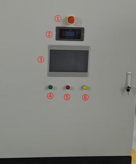
 

Continue
Home Archives